Overview

The HDR4RTT Capture Software is the first component of the HDR4RTT pipeline and is responsible for capturing images from a high-speed camera. This software interfaces with the BitFlow SDK to capture from a CoaXPress camera using a BitFlow frame grabber.
Contents:
System Requirements
In order to execute this software the dependencies enumerated in here must be met.
Hardware Requirements
This software was compiled and tested with the following specific hardware:
- NVIDIA GPU (CUDA Compute Capability 6.1) – This software uses CUDA to process the acquired images. The software was compiled for
Compute Capability 6.1+and should work on any CUDA-enabled card with the same or higher version of this Compute Capability. A Quadro GPU is required to use the DirectGPU capabilities (tested with Quadro P4000), otherwise, any card will work (tested with GeForce 1080ti). - IO Industries Flare 12M180CCX – This software was tested with the IOI Flare 12M180CCX for image acquisition, being this camera configured for the required acquisition parameters. It should be possible to use any other CoaXPress camera with a proper Configuration File.
- BitFlow Cyton-CXP – To capture the images from the camera, the software uses a BitFlow Cyton-CXP frame grabber. The Software Requirements below show how to properly install the software that allows the use of this frame grabber.
Software Requirements
There are a number of specific software packages that need to be installed in order for the application to be executed.
Microsoft Visual C++ Redistributable 14 (x64)
- Visit the downloads page from Microsoft
- Download the
Visual Studio 2015, 2017 e 2019versionx64of the redistributable, which corresponds to version14. The download file should have thevc_redist.x64.exefilename - Install the downloaded file and follow the on-screen instructions
BitFlow SDK
The BitFlow Cyton-CXP frame grabber identifies itself as a unknown PCI Device on Windows Device Manager with the Hardware ID PCI\VEN_118D&DEV_7000.
Warning: Before installing newer versions of the SDK, the previous version has to be first uninstalled.
Follow the next steps to properly install the frame grabber:
- Visit BitFlow’s Downloads page
- On the table find and download the
BitFlow SDK 6.40ZIP under theApplications/SDKcategory - Extract the downloaded ZIP and install the SDK with the provided installation wizard. Follow the on-screen instructions
During the installation when asked for aSerial Number, if you are going to compile this software from source, please insert your frame grabber’sSerial Number, otherwise, keep the default0value to install a driver-only version of the SDK. If you install the driver-only version of the SDK by keeping the default0value and you later need the full SDK to compile the software from source, you have to completely uninstall the SDK and install again inserting theSerial Numberwhen asked. - Restart the computer
- After restarting, if you go to Windows Device Manager, you should no longer see an unknown PCI Device. You should be able to find the
BitFlow Cyton-CXP4installed and working properly underImaging Devices
IO Industries Flare Camera Software (Optional/Recommended)
If you are using an IO Industries Flare Camera (like the Flare 12M180CCX), it is usefull to install its independent drivers in order to control the camera without the Capture Software.
Warning: This requires an IO Industries account. The account is free, but you will be asked for details on your Company, Job Title, and how you relate to IO Industries during the registering process.
- Go to IO Industries’ downloads page
- Under the
Camerassection, download the packageFlare Camera Software (64-bit) - Install the downloaded installation wizard, by following the on-screen instructions.
GenICamTM Package (Optional/Recommended)
For cameras that use the Generic Interface for Cameras (GenICam) like the Flare 12M180CCX, you can use the free GenICam Package that includes tools to configure the camera in a Plug & Play way.
- Go to Bitflow’s downloads page
- On the table find and download the
Ximilon GenTL ConsumerZIP under theCamera Controlcategory - Extract the downloaded ZIP and install the software with the provived installation wizard. Follow the on-screen instructions
Camera Configuration
The use of the software requires the camera to be configured through a specific mode defined on a camera file. Here we detail how to configure the camera using the configuration file. This camera file will be used by the frame grabber to operate the camera.
Requirements
To understand the configuration file and easily be able to edit it, please have the following:
- A copy of your camera manual to check what registers on the camera are used to the specific properties shown bellow and their correct values. For the Flare 12M180CCX, go to its downloads page and download the document
Flare 12MP CoaXPress User’s Manual. - The complete installation of the
BitFlow SDKwhich contains theCamMLapplication. This application is used to easily and graphically edit the camera file. Go to Software Requirements to see how to install theBitflow SDK. - (Optional but Recommended) The Camera independent drivers which contain the
CX-CL Controlapplication.
Camera File Template
A template camera configuration file pre-configured for the Flare 12M180CCX is provided in the Downloads. The following are included:
IOIndustries-Flare-12M180CCX-QuadCXP5.bfml: This is the main configuration file for the Flare 12M180CCX and is the file that should be used in the Capture Software when askedBFML-CXP.xsd: This is the schema file for the configuration file. Included in case it is needed
Camera File Operation Modes
he IOIndustries-Flare-12M180CCX-QuadCXP5.bfml includes the following operation modes:
- Default: This is the main mode used to preview the camera image on the
BitFlow Previewapplication. It is a free-run mode, where the camera is continuously capturing images. - Timed: This mode is used by the Capture Software for operations where only 1 exposure stack is required. It is an edge-triggered mode, where the camera captures a set of images when manually triggered. If you preview this mode using CamML, press the “Software Trigger” button to capture the images and the last exposure should appear on the preview.
- Timed_Cir: This mode is used by the Capture Software for Capture. It is a clone of the Timed mode, but with a different trigger condition. This cannot be previewed using CamML.
Camera File Structure and Contents
Open the IOIndustries-Flare-12M180CCX-QuadCXP5.bfml camera file with the CamML application. Once the file is open you should have a screen correspondent to the Camera settings.
The software allows to easily edit the camera file, and offers features like Clone and mode Preview.
Sections: Camera
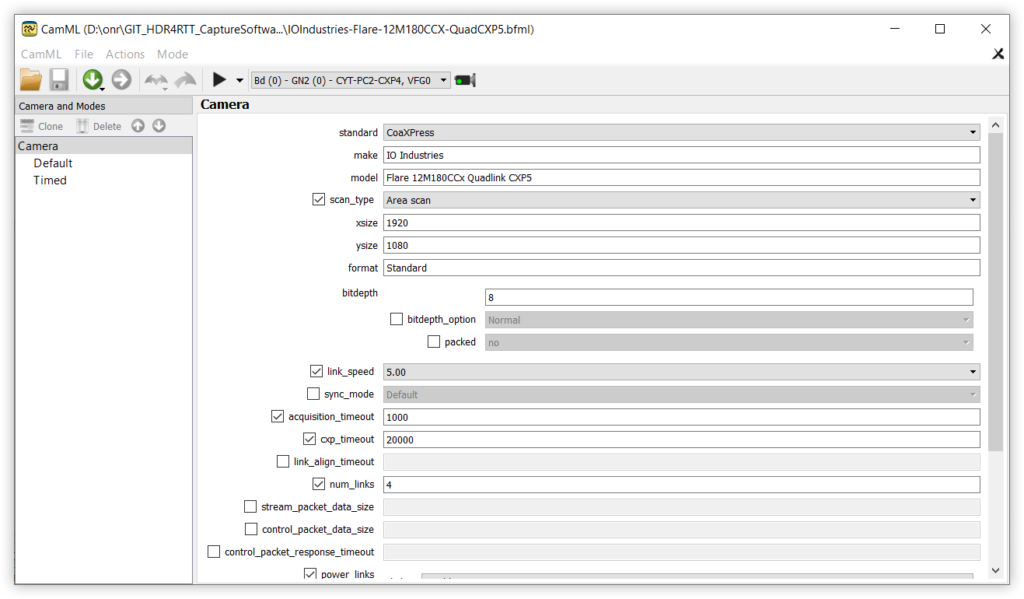
On the left, when the Camera option is selected, a set of settings that inform the frame grabber on what camera this file is for and how to use that camera will be presented.
As you can see, this file targets the IO Industries Flare 12M180CCx. The frame grabber outputs a 1280 * 720 image buffer in the standard format using a Area scan method on the sensor. The images will have 8-bit per pixel. The connection requires 4 phisical cable links between the frame grabber and the camera.
Sections: Default Mode
The Default mode is a free-run exposure mode. This means that the camera will start capturing and sending images to the frame grabber when it is armed.
From the available tabs in CamML, only the following ones are needed to this mode:
- device_commands: These are a set of device commands that will be executed before or after the camera setup. These commands are used to configure the camera using the GenICam Interface API instead of directly changing the camera low-level registers.
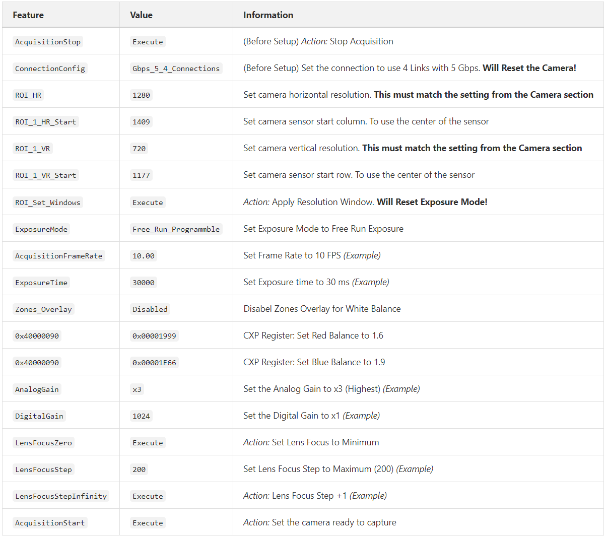
Tip 1: Use the
camera manual to find out the correct camera registers and values if needed.Tip 2: Use the
Ximilon GenTL Consumer when previewing this camera mode to change the camera values live and find the correct GenICam command names.Sections: Timed Mode
The Timed mode is a edge-triggered exposure mode. This means that the camera will be armed for capture and will stay idle until it receives a expected trigger. When this trigger is sent to the frame grabber, it will instruct the camera to take a set of exposures.
From the available tabs in CamML, only the following ones are needed to this mode:
- device_commands: These are a set of device commands that will be executed before or after the camera setup. These commands are used to configure the camera using the GenICam Interface API instead on directly changing the camera low-level registers.
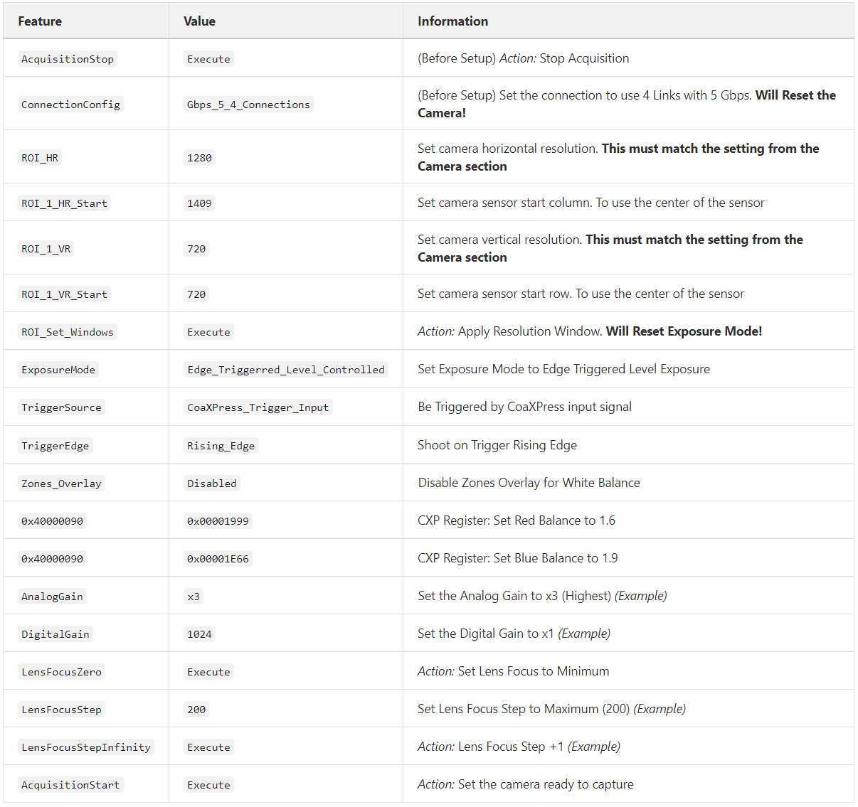
Tip 1: Use the
camera manual to find out the correct camera registers and values if needed.Tip 2: Use the
Ximilon GenTL Consumer when previewing this camera mode to change the camera values live and find the correct GenICam command names.- timing_sequencer: This is component responsible to set the exposure timings for each of the images to be capture in a set
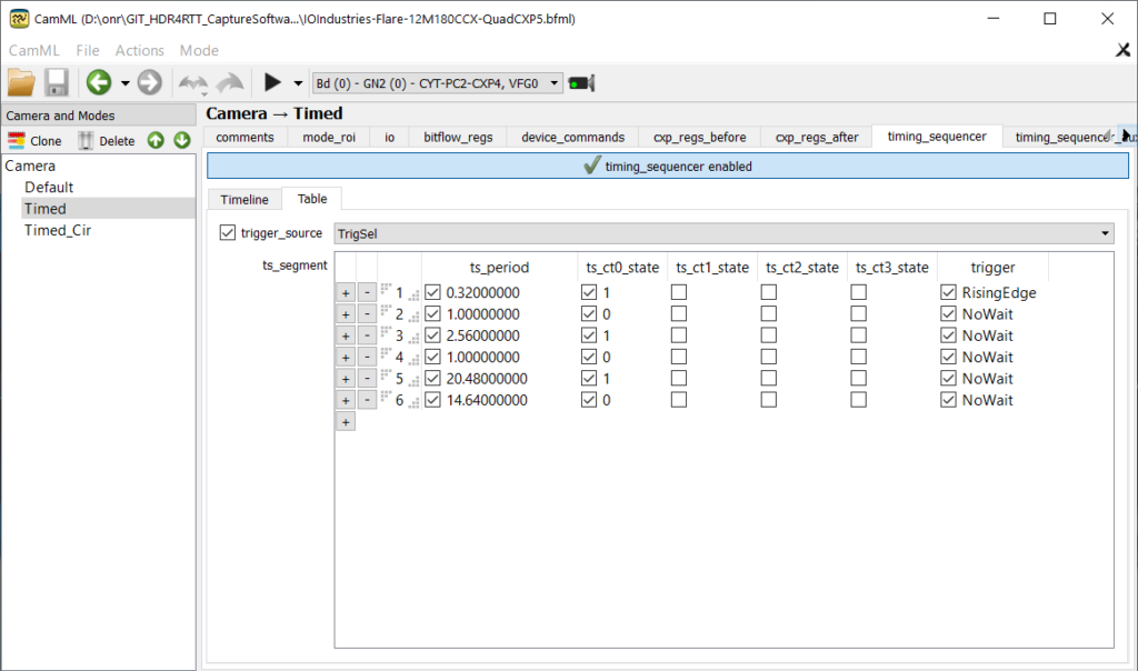
We set the trigger_source of the Timing Sequencer to the frame grabber’s selected trigger source (see io section below). This will allow us to start the Timing Sequencer by using this trigger.
The ts_segment is a table with all the timings for the camera in the form of timed pulses with their durations set in milliseconds. We configure the Sequencer entries to output their pulses to the CT0 State. While the Sequencer is outputting a high value (1) the camera is exposing an image and while it is outputting a low value (0) the camera will send the image to the frame grabber and idle until the next high pulse.
The template file (as shown in the image) is configured to capture 3 images for every set with the following exposure times: 0.32 ms, 2.56 ms, 20.48 ms.
The first exposure (0.32 ms) is set to begin whenever there is a high (1) pulse (RisingEdge) from the selected trigger (trigger_source). This way, we can ensure the capture of a set of images starts with the timing sequencer first exposure since we control when it begins sending the pulses. Otherwise, if we started the capture we might end up in an already running time sequencer and get any of the exposures.
Important: Note that the camera has a cool-down period between each image capture, where it reads the data from the sensor and sends it to the frame grabber’s buffer. We recommend using the provided spreadsheet to find this value.
The timings in this table control the frame rate. The number of times the sum of all the entry times fits in a second (1000 ms) is the final frame rate for the Capture Software. To target 25 fps, this template file uses 14.64 ms for the last idle period instead of 1 ms.
Tip: Preview the Default mode and use the CX-CL Control application to find the best exposure timings. Be careful that the CX-CL Control application measures the exposure time in microseconds. You also may need to lower the frame rate to be able to increase the exposure timings.
- io: Here the frame grabber’s I/O is set in order to support the triggered operation:
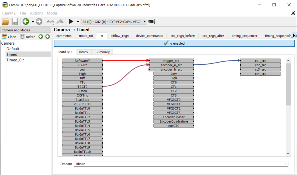
There are two things that are set up here:
First, we set the Software trigger as the selected trigger source by plugging its output to the trigger_src input. This will allow to fire a software trigger to start the capture and is done in order to ensure the sequence of images are captured in correct order (the order they are programmed in the Timing Sequencer).
Secondly, we route the Time Sequencer CT0 output through the Encoder A which is then connected to the camera’s first link (represented by cc1_src). This way, while the Timing Sequencer outputs a high pulse to CT0, the camera will expose and capture an image.
Sections: Timed_Cir Mode
This mode is a clone from the Timed mode. The Timed_Cir mode is a edge-triggered exposure mode. This means that the camera will be armed for capture and will stay idle until it receives a expected trigger. When this trigger is sent to the frame grabber, it will instruct the camera to take a set of exposures.
IMPORTANT: This mode’s name must be the same as the previous one, but with _Cir added in the end.
From the available tabs in CamML, only the following ones are needed to this mode:
- device_commands: These should be a copy of the ones from
Timedwith the following added before the “AcquisitionStart” command:
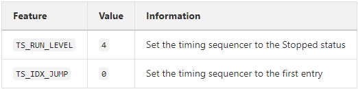
- timing_sequencer: This is component responsible to set the exposure timings for each of the images to be capture in a set. As before, it must have the same values as the
Timedmode. However, the first entry condition is changed toHigh. This way, the sequence will only start when the selected trigger is set to high (1) and continue cycling until it is set to low (0). - io: Here the frame grabber’s I/O is set in order to support the triggered operation:
Compared to the Timed mode, we change the tigger_src from Software to Low. This will be se to High in the Capture Software code.
Camera File Modifications
We recommend the use of the Default mode in preview mode with the Ximilon GenTL Consumer or CX-CL Control application to find and fine-tune the different camera parameters with a live preview.
Have the camera manual to check which registers are available to configure the camera and their correct values.
If you want to create a new Timed mode, we recommend you to Clone the template Timed mode and modify the new clone instead of the original one. This way you always have a fixed starting point.
Don’t forget that the horizontal and vertical resolution in the Camera Section and in the camera registers must match.
Usage
Application Mainscreen
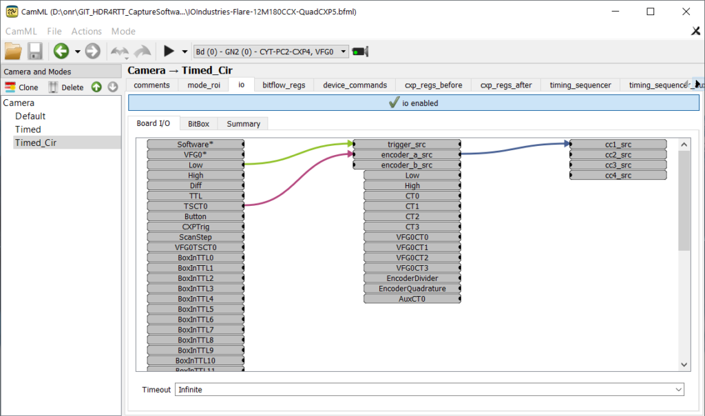
Once you installed the required packages for the Capture Software to be executed, you should be able to open it’s executable HDR4RTT_Capture.exe and see the following window:
As you can see by the numbering on the buttons, there’s a linear progress to the application usage, with the application having 5 main commands. The application was programmed to not allow the execution of commands out of order.
The status bar and progress bar on the bottom will provide some information about the actions being executed.
Application Flow
The following flowchart describes a typical application usage, i.e. the order the available commands should be executed:
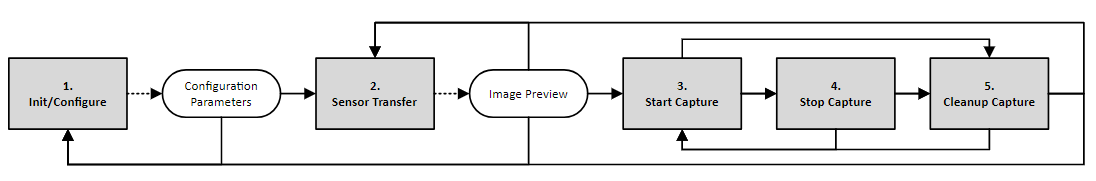
Application Commands
1. Init/Configure
The first command available is responsible for setting up and configuring the frame grabber and the camera.
This must be the first action to be executed everytime the software is opened.
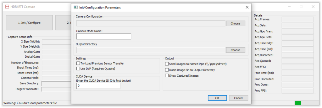
When you click this button a configuration window will open:
Note: The software will load and save these parameters to a configuration file next to the application executable parameters.cfg. This dialogue will be auto-populated with the previously saved parameters (if the configuration file exists) and will save the parameters to the same file when the dialogue is closed by pressing OK.
Here you are asked for a few parameters required for the configuration:
- Camera File: The first field is the path for the
Camera File. Use the Browse button to the right and pick a camera configuration file.bfml. The full path to the file should appear in the field. - Camera Mode Name: Here you must enter the
Timedmode name that is available on your camera file. - Output Directory: Here you must Choose a working directory for the software to use. Currently, this is used to store the Transfer Function of the camera and the captured images if chosen. Make sure your user has Read and Write privileges to this folder. Once you choose a folder, its full path should appear in the box.
- Try Load Previous Sensor Transfer: Enable this option to try and load previous sensor transfer values from the disk. If this doesn’t exist, a new Sensor Transfer will be calculated and saved. If you wish to force a new calculation, uncheck this option. NOTE: Currently the software is ignoring this parameter and using a linear sensor transfer function.
- Use DVP: Check this option if you want the software to use Nvidia’s DirectGPU technology. Requires a Quadro GPU.
- CUDA Device: This parameter allows to choose which CUDA device on the system will be used by this software.
0is the first and default device. - Send Images to Named Pipe: When this option is selected the captured images will be sent synchronously through a named pipe
\\.\pipe\hdr4rtt. - Dump Image Bin to Output Directory: When this option is selected the captured images will be saved synchronously to the disk in the binary format of
width * height * channels * sizeof(float). - Show Captured Images: When this option is selected the captured HDR image will be tone mapped and shown on the screen.
NOTE: The output options can be used simultaneously, however, keep in mind that due to the save process an error in one of the outputs will prevent the other ones from executing. The order is Show > Sent to Pipe > Save to Disk. For this reason, it is advised to only use one of the options.
Once the parameters are filled, you should see something like this (Example):
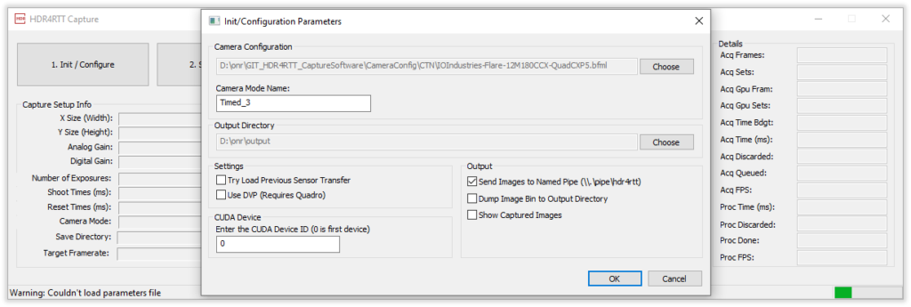
If you press OK, some sanety check will be performed, and the software will try to configure the frame grabber and camera with the provided parameters.
Firstly, you will see BitFlow’s window to choose the virtual frame grabber (VFG):
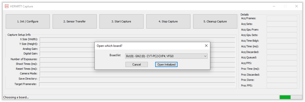
If you only have one camera connected to the frame grabber, you must choose the first VFG0. Otherwise, choose the virtual frame grabber that the camera is connected to.
After clicking Open Initialized, the software will open the frame grabber with the chosen camera file and configure the camera with commands set in the camera mode. You should see the progress and operation status at the bottom of the main screen. A success message should appear once the configuration is completed without errors.
Warning: Due to the nature of the connection, it is possible you get an error during the configuration along the lines of “Couldn’t initialize board.”. Press Next on the error dialogue and try Init/Configuring again. Also, restarting the Capture Software, or resetting the camera may help. Currently, it is not clear the root cause of this error.
1.1 Capture Information
If the board and camera are successfully configured, the current settings should appear on the Capture Software’s main screen. These must match the ones on the camera file for the chosen mode:
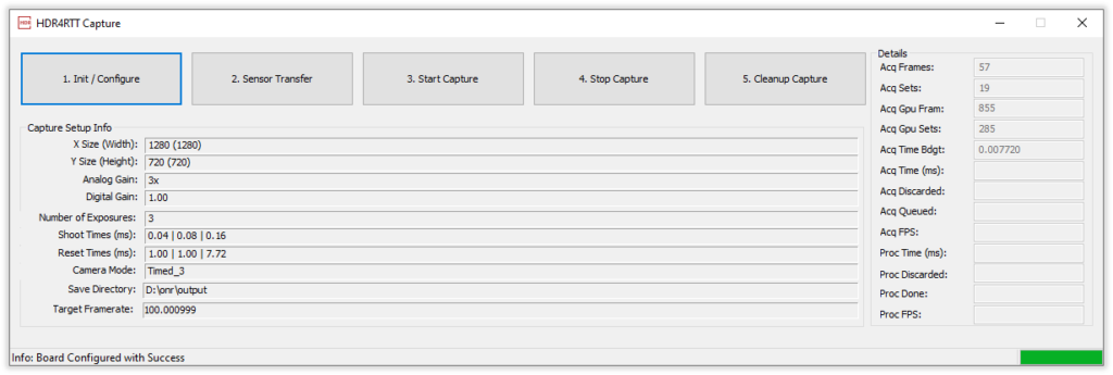
The followind data is available:
- X Size (Width): This is the horizontal resolution in pixels of the frame grabber buffer and in parenthesis the camera horizontal resolution. The two values must match for the final image to have the desired resolution and not be deformed.
- Y Size (Height): This is the vertical resolution in pixels of the frame grabber buffer and in parenthesis the camera vertical resolution. The two values must match for the final image to have the desired resolution and not be deformed.
- Analog Gain: This is the camera sensor’s analogue sensibility (Gain). Can be {1,2,3}x.
- Digital Gain: This is the camera sensor’s digital sensibility (Gain). The final gain is equal to Analog * Digital. This value is the value set on the camera file divided by 1024.
- Number of Exposures: This is the number of LDR images in a set and is calculated by the High (1) pulses on the board’s Timing Sequencer.
- Shoot Times (ms): These are the exposure times for each of the LDR images in a set. Obtained from the board’s Timing Sequencer.
- Reset Times (ms): These are the times in between each LDR image in a set. Obtained from the board’s Timing Sequencer.
- Camera Mode: Here you can see the camera mode that the board and camera are using.
- Save Directory: This is the complete path to the software’s working directory.
- Target Framerate: This is the target framerate for the final sets. Obtained from the Shoot and Reset times.
1.2 Details
Acq FPSFinal target framerate for the current camera configurationAcq FramesHow many raw frames fit in memory (Buffer Size)Acq SetsHow many sets fit in memory (Frames / Nº of Exposures)Acq Gpu FramHow many frames fit in GPU memory (GPU Buffer Size)Acq Gpu SetsHow many sets fit in GPU memory (Gpu Fram / Nº of Exposures)Acq Time BdgtWaiting time at the end of an exposure stack (last reset time).Acq Time (ms)The time it is tacking to acquire the imagesAcq DiscardedNumber of discarded sets because the processing is busyAcq QueuedNumber of sets sent to processingAcq FPSNumber of sets per second acquired and sent to processingProc Time (ms)The time it is tacking to process the set (merging and sending/saving)Proc DiscardedNumber of sets discarded after processing (failed to send/save)Proc DoneNumber of sets successfully sent/savedProc FPSNumber of sets per second successfully sent/saved
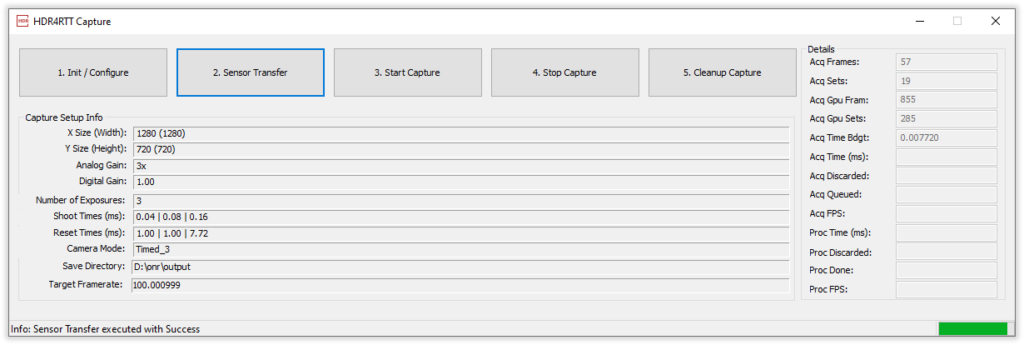
2. Sensor Transfer
IMPORTANT: As of now, and after trying different configurations, this step is only there to check a preview of the final images that will be captured and not processing the actual Transfer Function. We verified better final images with a linear Transfer Function.
Since the sensor transfer function is not linear, it is necessary to calculate it in order to correctly merge the LDR images into an HDR image.
After Init/Configuring, press the 2. Sensor Transfer button to calculate a new Sensor Transfer Function.
The camera will take a set of LDR images as defined in the Timing Sequencer.
After this:
- If you checked the
Try Load Previous Sensor Transferduring the first configuration, this step will look for a Sensor Transfer data from a previous calibration on the software’s working directory. If this file exists and is valid, the transfer function will be loaded. - If you did not check the
Try Load Previous Sensor Transferor the loading failed the software will calculate and save to disk a new transfer function using the LDR images.
WARNING: If all the LDR images are black, the software will not be able to calculate the transfer function and will freeze. You will have to manually terminate the process and start over again. If this happens, check and preview the Timed mode.
Once the software has a Transfer Function, it will merge the priviously obtained LDR images into an HDR image and create a tone mapped version as well.
The tone mapped HDR image will be displayed so the user can check for erros in the image:
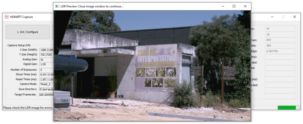
The preview window must be closed to continue, and a success message should appear in the status bar:
If the image was defective, try to obtain a new Sensor Transfer Function by pressing the same button again. If the Try Load Previous Sensor Transfer is checked, you will have to uncheck it to obtain a new function.
3. Start Capture
Once sensor transfer function is executed with success you can Start the capture.
Click the 3. Start Capture button and the software will arm the camera and start capturing frames, as you can see on the Details panel.
If you configured the software to send images through a pipe, after clicking this button, the software will wait for the pipe client to connect. Only after this, it will proceed with the capture.
4. Stop Capture
If for any reason you want to pause the capture temporarly, you can press the 4. Stop Capture button.
This will halt the image acquisition. If you then press the 3. Start Capture button, the image acquisition should resume.
5. Cleanup Capture
When you are done with the capture, you can press the 5. Cleanup Capture button.
Downloads
Here you can download the Capture Software assets: